
What Are Tolerances in CNC Machining?
When we talk about tolerances in CNC machining, we’re simply talking about how much a real part is allowed to deviate from the nominal CAD dimension and still be accepted.
For precision 5-axis milling, these limits define your CNC part dimensional accuracy, cost, and risk.
Dimensional Tolerances for 5-Axis Parts
For 5-axis CNC parts, dimensional tolerances set the allowed variation in size and location of features such as:
- Hole diameters, slot widths, wall thickness
- Distances between faces, holes, or pins
- Angles between planes on complex 5-axis geometry
Example:
- Nominal: Ø10.00 mm
- Tolerance: ±0.01 mm
- Acceptable range: 9.99–10.01 mm
These dimensional limits are the core of standard tolerances for 5-axis parts and sit alongside more advanced geometric controls.
Linear vs Geometric Tolerances in Multi-Axis Machining
In multi-axis machining, we use both:
- Linear tolerances
- Control size or distance (e.g. 50.00 ±0.02 mm)
- Simple, easy to read, often in a title block or CNC tolerance chart
- Geometric tolerances (GD&T)
- Control shape and relationship between features
- Use symbols for flatness, position, perpendicularity, runout, etc.
- Critical for complex 5-axis surfaces and multi-axis tolerance stack-up
Geometric tolerances are what really unlock 5-axis machining accuracy for demanding aerospace, medical, and automotive components.
Bilateral, Unilateral, and Limit Tolerances
We typically see three ways of writing size tolerances:
- Bilateral tolerance
- Variation allowed both plus and minus
- Example: 20.00 ±0.05 mm (range: 19.95–20.05 mm)
- Unilateral tolerance
- Variation allowed only in one direction
- Example: 20.00 +0.00/-0.05 mm (range: 19.95–20.00 mm)
- Useful when a part can only be smaller (e.g. shaft into a bearing)
- Limit tolerance
- Only upper and lower limits shown
- Example: 19.95–20.05 mm with no nominal listed
We work with all three, depending on whether you care more about clearance, interference, or minimum wall thickness.
How These Concepts Apply to 5-Axis CNC Parts
On 5-axis CNC machines, the same tolerance concepts apply, but the stakes are higher because features are often:
- Machined in a single setup, at compound angles
- Linked in 3D space with tight positional and angular tolerances
- Sensitive to tolerance stack-up in CNC when they must line up in assemblies
That’s why for precision 5-axis parts we usually combine:
- Reasonable standard linear tolerances for general features
- Targeted GD&T controls (position, flatness, angular tolerances in machining) for critical interfaces
Used correctly, these tolerancing basics let us deliver reliable, high-precision 5-axis CNC tolerances without unnecessary cost.
Why Standard Tolerances for 5-Axis Parts Matter
Tolerances matter more in 5-axis machining because these parts usually sit at the heart of complex systems: turbines, implants, high-speed spindles, electronics housings, and safety-critical assemblies. If the dimensional accuracy is off, the whole system pays the price.
5-Axis Cuts Setup Count and Stack-Up
With 5-axis CNC, we machine more faces in a single setup. That means:
- Fewer clamp/unclamp cycles
- Less re-location error
- Lower tolerance stack-up across multiple features
This lets us hold tighter “overall” dimensional accuracy on complex geometries than with traditional 3-axis workflows.
5-Axis vs 3-Axis Tolerance Capability
Typical comparison for precision milled parts (depending on material, size, and process control):
| Process | Typical Linear Tolerance* | Angular Tolerance* |
|---|---|---|
| 3-axis CNC milling | ±0.01–0.02 mm | ±0.1–0.2° |
| 5-axis precision milling | ±0.005–0.01 mm | ±0.05–0.1° |
*Reference values for guidance only. Final tolerances depend on part and setup.
This tighter capability makes 5-axis machining ideal for high-precision CNC services where multi-axis tolerance stack-up must be controlled.
What Loose Tolerances Really Cost
Loose or uncontrolled tolerances on 5-axis parts can cause:
- Poor fits, leaks, and vibration in assemblies
- Imbalance and noise at high RPMs
- Reduced life for bearings, gears, and cutters
- Rework, scrap, and unpredictable performance
In sectors like aerospace machining tolerances, even small deviations can mean a failed test or grounded hardware.
Regulatory and Industry Pressure
Global customers often work under strict standards and audits. For many 5-axis CNC parts, we need to align with:
- ISO and ASME tolerance standards
- Aerospace (AS9100), medical (ISO 13485), and automotive (IATF 16949) expectations
- Documented process control, machine calibration, and CMM inspection
For electronics and lightweight housings, we balance weight, space, and CNC part dimensional accuracy, similar to our work in precision electronics machining projects.
Cost vs Performance: Finding the Sweet Spot
Not every feature needs ultra-tight tolerance machining. Pushing everything to ±0.005 mm drives up cost without always adding value. Our approach:
- Tight tolerances only on critical interfaces and high-speed features
- Standard tolerances for non-critical faces and cosmetic areas
- Clear CNC tolerance chart guidance during DFM review
This way, we keep your standard tolerances for 5-axis parts realistic, control cost, and still deliver the performance you designed for.
Standard Tolerances for 5-Axis CNC Parts
When we talk about standard tolerances for 5-axis CNC parts, we’re usually working in a practical, repeatable range that balances accuracy, cost, and lead time.
Typical Standard Tolerance Ranges
For most 5-axis CNC milling work, a realistic general dimensional tolerance is:
- ±0.005–0.01 mm (±5–10 μm) on critical features on stable materials
- ±0.02–0.05 mm on non-critical or larger dimensions
These values assume a well-calibrated machine, proper fixturing, and controlled environment like we use in our own high-precision 5-axis machining setups.
ISO 2768 Tolerance Classes in 5-Axis Machining
If you don’t specify anything else, many shops default to ISO 2768 for “general tolerances”:
- ISO 2768-m (medium) – common for general machined parts
- ISO 2768-f (fine) – used for tighter, precision components
For 5-axis parts, ISO 2768-f is often the better choice when your part has complex freeform surfaces, multi-axis holes, or critical interfaces.
IT Grades for Precision Fits
For very tight fits and precision assemblies, we look at IT (International Tolerance) grades:
- IT09–IT07 – typical for quality machined parts
- IT07–IT05 – high-precision fits, sliding fits, guided motion
- IT05–IT01 – ultra-precision, usually needs grinding, lapping, or honing
On 5-axis parts, we can often reach IT07–IT05 directly from machining on key features, then add secondary finishing if you need IT01–IT03 in specific zones.
Standard Angular Tolerances in 5-Axis
Angular accuracy is a big deal on multi-axis parts:
- Standard angular tolerance: ±0.1°–±0.2° for general surfaces
- Tight angular tolerance: ±0.02°–±0.05° on critical faces, angled holes, and seating surfaces
Good 5-axis machines with proper rotary calibration and probing can hold small included angles and compound angles consistently.
Surface Finish vs Tight Tolerances
Tight tolerances and surface finish go hand in hand. Typical ranges:
- Ra 1.6–3.2 µm – general machined surfaces
- Ra 0.8–1.6 µm – precision functional surfaces
- Ra 0.2–0.4 µm – sealing surfaces, optical or medical-grade zones (usually requires polishing or grinding)
When you ask for very tight tolerances, expect stricter surface finish control, more process steps, and added inspection.
Typical Tolerances by Industry
Different industries push tolerance limits in different ways:
- Aerospace:
- Dimensions: often ±0.005–0.02 mm on interfaces and hole positions
- Angular: as tight as ±0.02°–0.05° on mating surfaces and blade profiles
- Medical (implants, surgical tools):
- Dimensions: ±0.005–0.01 mm on implants, mating features, and small geometries
- Surface: very clean low Ra to avoid tissue irritation and for easy cleaning; see how we handle this on our medical machining projects
- Automotive:
- Dimensions: often ±0.01–0.05 mm depending on safety/engine components vs structural parts
- High-volume parts prioritize repeatability, which we address in our automotive machining services
When to Use Standard vs Custom Tight Tolerances
Use standard tolerances when:
- The feature is non-critical (covers, non-mating surfaces, cosmetic areas)
- The part is not running at high speed or under heavy load
- Cost and lead time are more important than extreme precision
Specify custom tight tolerances when:
- The feature is part of a precision assembly, sealing surface, or alignment interface
- The part runs at high speed, high load, or safety-critical (aerospace, medical, drivetrain)
- You need repeatable positioning and motion (robotics, actuators, guides)
In practice, the best approach is to keep only truly critical features tight, and leave the rest at standard ISO 2768 ranges. That’s how we keep your 5-axis parts accurate without making them unnecessarily expensive.
Factors Affecting Tolerances in 5-Axis Machining
When we talk about standard tolerances for 5-axis parts, the real limit is not just the machine spec – it’s the whole system: material, setup, tools, and environment. Here’s what actually controls how tight we can go.
Material & Thermal Expansion
Different materials move a lot with temperature, and that directly hits 5-axis CNC tolerances:
- Aluminum and plastics expand more than steel or titanium.
- Large parts or thin-walled parts will “breathe” with even a small temperature change.
- Coolant temperature and cutting heat can shift dimensions while we’re machining.
For high-precision work, we match the material behavior with the right process and, if needed, use stable engineering plastics like PEEK or PTFE with known thermal characteristics in our material machining workflow.
Part Geometry & Feature Complexity
Complex 5-axis geometry makes tolerances harder to hold:
- Deep cavities, long reach pockets, and thin walls are more prone to vibration and deflection.
- Freeform surfaces and multi-angle features make geometric tolerances (position, profile, runout) more sensitive.
- The more simultaneous axes moves in one feature, the more important machine rigidity and strategy become.
We usually combine smart toolpaths, staged roughing/finishing, and local rest machining to stabilize dimensions on complex 5-axis parts.
Tool Wear, Tool Holding & Spindle Stability
Tooling directly drives 5-axis machining accuracy:
- Long, small-diameter tools deflect more and wear faster.
- Poor tool holders, runout, or dirty tapers kill tight tolerance machining.
- Spindle bearings and thermal growth in the spindle affect both size and surface.
To keep CNC part dimensional accuracy tight, we focus on:
- High-quality holders and balanced tools
- Short tool stick-out wherever possible
- Scheduled tool changes for critical features
Machine Calibration, Probing & Compensation
For high-precision 5-axis milling, calibration is non-negotiable:
- Kinematic calibration aligns rotary axes with linear axes.
- On-machine probing lets us auto-correct work offsets and tool length/radius.
- Thermal compensation adjusts for machine growth over long runs.
We use probing and compensation in-cycle so the machine corrects itself instead of relying only on manual adjustments or post-process fixes.
Shop Environment & Temperature Control
You can’t chase microns in a bad environment:
- Temperature swings in the shop directly change CNC tolerances on the part.
- Drafts, sun on the machine, or hot chips building up all add variation.
- Stable climate + stable coolant = more repeatable 5-axis parts.
For tight tolerance work, we hold a controlled temperature range around both the machines and metrology area.
Process Parameters & Cutting Strategy
Feeds, speeds, and toolpaths decide how close we get to the drawing:
- Heavy roughing → more heat and deflection → rougher tolerance.
- Light finishing passes → smoother cuts and more stable size.
- Climb milling, constant-engagement toolpaths, and proper step-downs improve both accuracy and surface finish.
We often split cycles into rough + semi-finish + finish, especially where GD&T for 5-axis parts calls for tight form and profile.
Cost Impact of Ultra-Tight Tolerances
Every micron costs money. Tightening tolerances affects:
- Cycle time: more passes, lower feed, more probing.
- Tooling costs: premium tools, more frequent tool changes.
- Inspection time: more CMM checks and documentation.
- Scrap rate: less margin for variation.
Our rule:
- Use tight tolerances only where function or assembly requires it (bearing fits, sealing surfaces, precision bores).
- Keep standard tolerances for non-critical areas to control cost and lead time for your 5-axis CNC projects.
When you share your drawings with us, we’ll often highlight where tolerances can safely be opened up without hurting function – that’s the fastest way to hit the sweet spot between precision and cost on 5-axis machined parts.
How to Specify and Achieve Tight Tolerances in Your Designs
Choose realistic standard tolerances for 5-axis parts
Start from function, not from “as tight as possible.” For most precision 5-axis CNC parts, standard tolerances like ±0.01–0.02 mm on non-critical dimensions give excellent CNC part dimensional accuracy without blowing up cost.
To keep 5-axis CNC tolerances realistic:
- Use standard tolerances for general features (holes, bosses, pockets)
- Tighten only where fit, sealing, or motion requires it (bearings, interfaces, flow paths)
- Share a simple CNC tolerance chart or table instead of repeating notes all over the drawing
If your tolerance depends heavily on material behavior, check our machining material selection and properties guide before you lock the numbers.
Use GD&T correctly on 5-axis drawings
GD&T for 5-axis parts should control function and avoid over-constraining:
- Define clear, functional datums that match how the part is clamped on the 5-axis machine
- Use position, profile, and orientation callouts instead of stacking linear dimensions
- Keep bonus tolerance and datum precedence simple so inspection and CMM programs stay robust
Clean GD&T is the fastest way to get consistent 5-axis machining accuracy across multiple batches.
Prioritize critical vs non‑critical features
Not every surface needs tight tolerance machining:
- Mark critical features (mating faces, bores, seal grooves, turbine or impeller surfaces) with tighter GD&T
- Relax non-critical surfaces (covers, cosmetic areas, clearance pockets) to standard tolerances for 5-axis parts
- Call this out clearly in a tolerance or color-coded model if possible
This keeps cost under control and focuses process capability where it matters.
Combine machining with secondary finishing
For ultra-tight features beyond normal precision 5-axis milling capability, we often:
- Rough/finish on 5-axis, then grind, hone, lap, ream, or EDM the final surfaces
- Leave a small, controlled stock allowance for the finishing process
- Agree on which dimensions are held by machining vs. finishing
This approach is common in aerospace machining tolerances and medical device machining tolerances where microns matter.
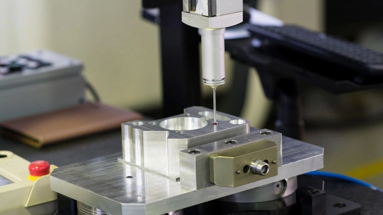
Use the right inspection methods for tight tolerances
When tolerances shrink, inspection has to keep up:
- Use CMM inspection for tight tolerances on complex 5-axis geometry and GD&T callouts
- Use optical or laser scanning for freeform surfaces and blended radii
- Use in-machine probing for in-process checks and to reduce tolerance stack-up in CNC
Always align your inspection plan with your drawing GD&T so there is no debate at acceptance.
Design & DFM tips for stable 5-axis tolerances
To improve design for manufacturability 5-axis and keep tolerances stable:
- Avoid very thin walls and deep, narrow pockets where tools deflect
- Add generous fillets and access for standard cutters
- Keep datum features stiff and easy to reach with the spindle
- Try to design parts so they can be fully machined in one or two 5-axis setups
These choices directly improve achievable 5-axis machining accuracy and repeatability.
Collaborate early with your machining partner
The best tolerance results come from early teamwork:
- Share 3D models, drawings, and your functional requirements up front
- Ask us to flag risky dimensions and propose more robust standard tolerances for 5-axis parts
- Align on inspection reports, measurement methods, and sampling before production
If you already have a design in mind, you can request a quote with your tolerance requirements and we’ll respond with practical options on cost, process, and achievable tight tolerance machining.
Common Pitfalls in 5-Axis Tolerance Specification and Control
Over-tightening tolerances where they aren’t needed
One of the fastest ways to drive up cost and lead time is calling out ultra-tight tolerances on non-critical features. Not every pocket, chamfer, or cosmetic surface needs ±0.005 mm.
When we quote 5-axis CNC parts, we always ask:
- Does this feature affect function, sealing, or fit?
- Is it a mating or locating surface?
If not, we keep it at standard machining tolerances. That keeps your price reasonable while still protecting critical performance.
Ignoring material behavior and anisotropy
Metals and plastics don’t behave the same once they leave the machine. Aluminum, steel, and plastics like POM or ABS move differently with stress relief and temperature. For example, thin walls in aluminum or anisotropic plastic parts can shift after machining.
When we recommend materials from our metal CNC machining range or plastic materials lineup, we factor in:
- Thermal expansion
- Internal stress and warping
- Fiber direction or anisotropy (for some plastics)
Underestimating setup, fixturing, and validation
5-axis machines reduce setups, but complex parts still need smart fixturing and validation. Tight tolerance machining demands:
- Rigid, repeatable fixturing
- Correct part orientation for each critical feature
- Verification runs and in-process checks
If the fixture or setup isn’t rock solid, even the best 5-axis machine won’t hold the tolerance you’ve drawn.
Miscommunication between design and manufacturing
A lot of tolerance problems come from drawings that don’t match real-world manufacturing. Common issues:
- No clear datum structure
- Mixed or unclear GD&T symbols
- Tolerances that conflict with each other
We push for early engineering review: we go through your CAD/drawings together, align on critical features, and confirm what tolerances are truly required for assembly and function.
How a robust process avoids rework and failed parts
The way to avoid scrap, rework, and late deliveries is a stable, repeatable process, not just a “tight machine.” Our approach:
- Define realistic tolerances and GD&T up front
- Choose the right material and machining strategy
- Use in-process probing and final inspection (CMM, gauges)
- Lock in proven setups for repeat orders
That’s how we keep 5-axis parts within spec, batch after batch, without surprise costs or failed assemblies on your side.