

What Is Geometric Dimensioning and Tolerancing (GD&T) in Battery Manufacturing?
Geometric Dimensioning and Tolerancing (GD&T) is a standardized symbolic language used on engineering drawings to explicitly define the allowable variation in geometry, size, orientation, and location of battery components. In battery end plate machining, GD&T guarantees that precision-machined structural parts align perfectly with battery modules and enclosures during electric vehicle manufacturing.
Understanding the Fundamentals of GD&T
GD&T shifts quality control from basic coordinate dimensions to functional geometric control. It uses precise mathematical tolerance zones to ensure parts fit together seamlessly during high-volume production.
| GD&T Core Element | Function in Battery Machining | Key Benefit |
|---|---|---|
| Datum Feature | Establishes reference points, axes, or planes on the end plate | Ensures consistent machining reference baselines |
| Feature Control Frame | Defines geometric controls (flatness, position, profile) | Provides clear, standardized tolerance requirements |
| Material Condition Modifiers | Adjusts tolerances based on actual feature size | Maximizes manufacturing tolerance without compromising fit |
The Role of GD&T in Standardizing Battery Part Specifications
Standardizing battery end plate specifications through GD&T eliminates design ambiguity between engineering teams and CNC machining operations. Replacing traditional plus/minus tolerances with functional geometric boundaries secures critical performance benchmarks across production facilities:
- Component Interchangeability: Ensures battery end plates fit uniformly across global assembly plants regardless of production origin.
- Drawing Clarity: Replaces subjective interpretations with universal standards (ASME Y14.5 / ISO 1101).
- Cost Optimization: Expands usable manufacturing tolerances where functional fit permits, reducing scrap and machining rework.
Why GD&T Is Critical for Battery End Plate Machining
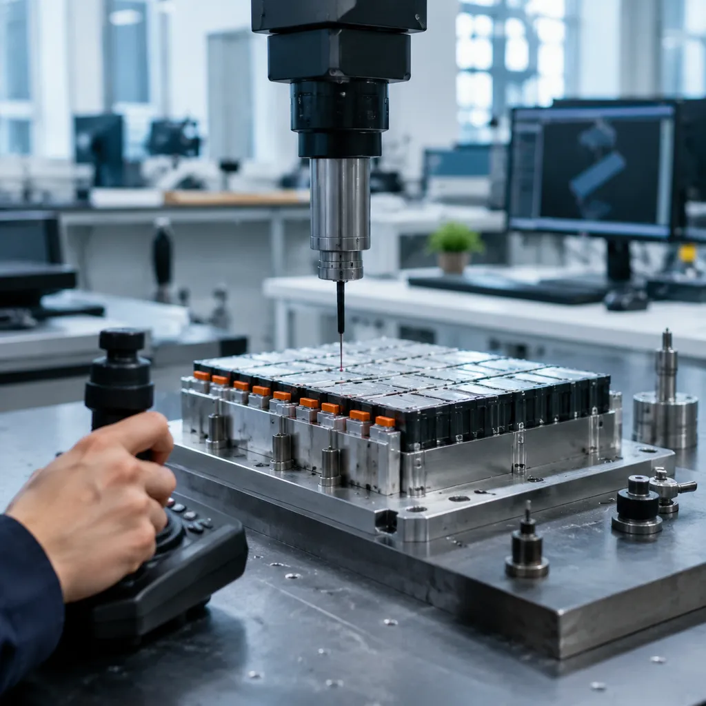
Machining battery end plates requires extreme precision because these components act as the primary structural anchor for EV battery modules. Applying GD&T in battery parts allows us to establish exact mechanical boundaries, ensuring that every end plate withstands high physical stresses while keeping the internal cells tightly sealed and aligned.
Ensuring Structural Integrity and Safety
Battery end plates must contain the natural swelling of lithium-ion cells during charge and discharge cycles without flexing or failing.
- Uniform Stress Distribution: Strict flatness and perpendicularity controls prevent localized pressure points on the battery cell stack, avoiding internal short circuits.
- Thermal Management Alignment: Precise dimensional controls ensure consistent surface contact with cooling plates, maintaining optimal heat dissipation across the entire pack.
- Structural Containment: Precise position tolerance callouts on structural mounting points ensure the end plate absorbs severe road vibrations and crash impacts in electric vehicle manufacturing.
Enhancing Battery Pack Assembly and Module Integration
In high-volume battery assembly, parts must fit together instantly on automated lines without manual tweaking.
- Flawless Component Interchangeability: GD&T defines clear tolerance zones relative to established datums, guaranteeing every end plate matches adjacent side rails, top covers, and cooling manifolds.
- Seamless Hole Pattern Matching: Accurate position controls on mounting holes eliminate bolt binding, reducing mechanical strain on fasteners during robotic installation.
- Efficient Automated Handling: Consistent geometric profiles allow automated pick-and-place systems to index parts reliably, speeding up overall pack assembly.
Optimizing Quality Control and Reducing Manufacturing Waste
Clear GD&T callouts remove guesswork on the shop floor, establishing unambiguous standards for quality inspection.
- Streamlined CMM Inspection: Defined feature control frames give quality teams exact parameters to measure on Coordinate Measuring Machines (CMMs), speeding up part sign-offs.
- Expanded Acceptance Zones: Utilizing Material Condition Modifiers (like MMC) gives machining operators extra tolerance as hole sizes depart from maximum material limits, reducing scrap without sacrificing function.
- Lower Scrap Rates: Combining clear geometric standards with proven strategies for managing manufacturing cost and quality keeps production yields high and material waste low.
- Consistent Quality Standards: Leveraging tight tolerances in CNC machining for automotive parts ensures that every machined end plate meets rigid safety and reliability benchmarks.
Core GD&T Concepts for Battery Parts Design
Applying GD&T in battery parts design requires a structured system to define exact geometric boundaries. We use core GD&T concepts to turn complex battery end plate engineering drawings into repeatable, high-precision manufactured components.
Datums and Reference Coordinate Systems
Datums form the theoretical foundation for all measurements on a battery end plate. Establishing a precise coordinate system ensures that machining, quality control, and assembly teams all measure from the exact same baseline points.
- Datum Feature: The actual physical surface, hole, or edge on the machined aluminum end plate used to establish the datum.
- 3-2-1 Rule Application: We establish a primary plane (3 contact points), a secondary line (2 points), and a tertiary point (1 point) to completely freeze all 6 degrees of freedom.
- Assembly Alignment: Proper datum selection guarantees that mounting faces, pin holes, and cooling channels align perfectly during module integration.
When setting up machining baselines for complex end plate geometry, adhering to standard tolerances for 5-axis parts ensures high precision across all CNC setups.
Understanding Feature Control Frames
The feature control frame is the rectangular symbol block on engineering drawings that communicates exact geometric requirements for every feature on a battery end plate.
| Block Component | Purpose in Battery End Plate Design |
|---|---|
| Geometric Symbol | Specifies the control type (e.g., Position, Flatness, Perpendicularity). |
| Tolerance Value & Zone | Defines the total allowable variation zone (often cylindrical, denoted by Ø). |
| Material Condition Modifiers | Adjusts tolerance limits based on actual feature size (e.g., MMC). |
| Datum References | Identifies the primary, secondary, and tertiary datums that orient the tolerance zone. |
Reading these frames accurately allows our CNC machinists to hold exact position tolerance on battery pack bolt holes, preventing alignment binding during final pack assembly.
Applying Material Condition Modifiers
Material condition modifiers refine how tolerances apply as physical feature dimensions vary within their allowable size limits.
- Maximum Material Condition (MMC - Ⓜ): Applied when a feature contains the maximum amount of material (e.g., smallest hole diameter or largest pin diameter). MMC grants "bonus tolerance" as hole sizes grow larger, ensuring fast assembly without sacrificing fit.
- Least Material Condition (LMC - Ⓛ): Applied when a feature contains the minimum amount of material. We use LMC on battery end plates to guarantee minimum wall thickness around lightweight pockets and high-pressure fluid channels, preventing structural failure.
- Regardless of Feature Size (RFS): The default condition where the geometric tolerance stays strictly fixed regardless of feature size. Used for high-precision mating faces and sealing surfaces.
In battery end plate manufacturing, combining these modifiers with aluminum 6061 design optimization keeps production costs manageable while maintaining exact component interchangeability.
Essential GD&T Symbol Categories and Characteristics
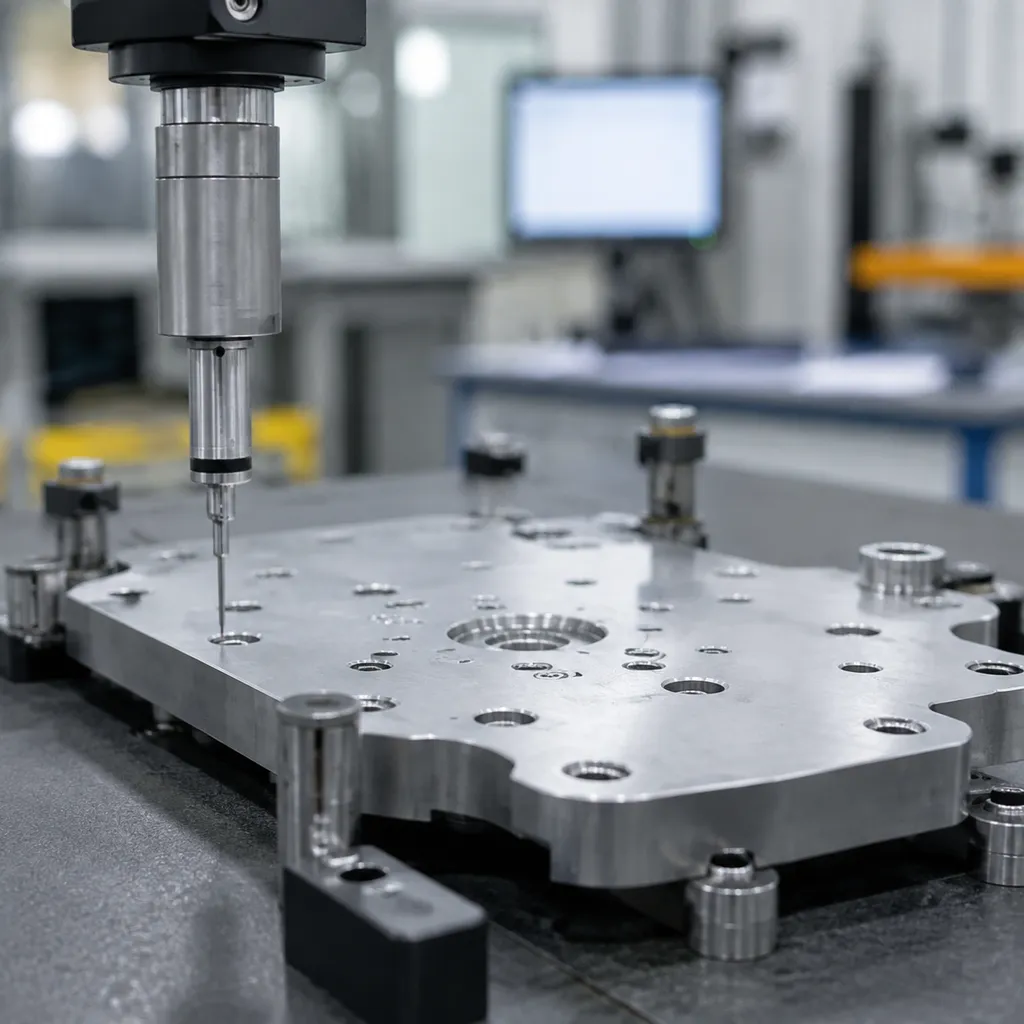
Applying standard geometric symbols on engineering drawings gives us precise control over how battery end plates are manufactured and inspected. In battery end plate machining, we group GD&T symbols into distinct functional categories to control individual shapes, orientations, positions, and surface variations.
Form and Orientation Controls
Form controls regulate the individual shape of a feature without referencing a datum feature, while orientation controls govern angular relationships between features.
- Flatness: Essential for sealing faces and thermal interface surfaces. Maintaining strict flatness prevents coolant leaks and ensures uniform heat transfer across cooling plates.
- Perpendicularity: Guarantees end plate sidewalls and mounting faces stay at exact 90-degree angles to primary baselines.
- Parallelism: Keeps opposing mating faces uniformly parallel, preventing uneven clamping pressure during module assembly.
Location and Profile Controls
Location and profile controls define exact feature locations and complex surface boundaries across critical GD&T in battery parts.
- Position Tolerance: Defines the exact center location for bolt holes and mounting features, ensuring accurate component interchangeability during automated pack assembly. Maintaining tight aluminum CNC machining tolerances ensures these hole patterns align perfectly every time.
- Profile of a Surface: Controls the entire 3D boundary of complex end plate contours to guarantee a snug fit inside tight EV battery enclosures.
- Profile of a Line: Regulates 2D cross-sectional profiles along specific critical cut lines or edge radii.
Runout Tolerances in Machined Components
Runout controls evaluate cumulative surface variations when rotating a feature around a central reference axis, vital for cylindrical locating elements.
- Circular Runout: Checks surface variations at individual circular cross-sections to maintain rotational accuracy.
- Total Runout: Controls the entire surface simultaneously, regulating both circularity and straightness along cylindrical mounting features.
- Concentricity: Verifies that the centerlines of cylindrical bores and alignment pins stay aligned with the primary datum axis.
| GD&T Category | Key Characteristics | Primary Function in Battery End Plate Machining |
|---|---|---|
| Form | Flatness, Straightness | Ensures leak-free sealing and uniform cooling contact. |
| Orientation | Perpendicularity, Parallelism | Prevents angular misalignment during high-voltage module integration. |
| Location | Position Tolerance | Guarantees perfect alignment for fasteners and mounting points. |
| Profile | Profile of Surface | Maintains strict exterior clearance within electric vehicle manufacturing enclosures. |
| Runout | Circular & Total Runout | Controls cylindrical variations on alignment dowels and pin locations. |
GD&T Tolerance Analysis for Battery End Plate Machining
Performing a rigorous GD&T tolerance analysis on battery end plates is essential to ensure structural safety, precise thermal management, and efficient pack assembly. Here is how we evaluate critical geometric callouts during precision machining.
Flatness and Profile Tolerances for Sealing Interfaces
Battery end plates serve as structural barriers and liquid-cooling sealing interfaces. Any warping across the mating surface risks coolant leaks and catastrophic thermal events.
- Flatness Control: We apply strict flatness tolerances across the perimeter sealing land to ensure uniform compression of gaskets and O-rings without over-torquing bolts.
- Surface Profile: Profile of a surface controls complex contours, ensuring consistent thermal contact between the end plate and adjacent cooling channels.
- Quality Control: In-line optical scanning verifies that machining stress relief does not bow thin-walled aluminum sections.
Position Tolerances for Mounting Holes and Fasteners
Accurate hole patterns prevent assembly line binding and uneven load distribution across the battery pack shell.
- True Position: We reference the primary datum feature scheme on engineering drawings to lock down hole locations within tight cylindrical tolerance zones.
- Component Interchangeability: Utilizing the Maximum Material Condition (MMC) modifier provides extra bonus tolerance when hole sizes move away from minimum limits, boosting yield while preserving fit.
- Production Consistency: Following strict automotive prototype machining standards helps us maintain repeatable fastener positioning across high-volume production runs.
Parallelism and Perpendicularity for Module Alignment
Proper alignment controls prevent mechanical stress on sensitive lithium-ion cells when compressing battery modules together.
| Feature Control | Functional Objective | Impact on Battery Pack |
|---|---|---|
| Perpendicularity | Keeps mounting faces exactly 90 degrees to primary datum surfaces | Prevents side-loading on module compression tie rods |
| Parallelism | Ensures opposing end plate faces remain strictly parallel | Maintains uniform cell pressure across the entire module stack |
| Concentricity / Coaxiality | Aligns multi-axis guide pins and structural bushings | Eliminates binding during automated module integration |
Correct application of these orientation controls ensures long-term structural durability and safety across demanding electric vehicle manufacturing applications.
Best Practices for Implementing GD&T in Battery Part Machining
Putting GD&T in battery parts design into real-world production requires tight alignment between engineering drawings and shop-floor execution. We focus on rigid process control to ensure every machined end plate meets exact tolerance callouts.
Aligning Machining Operations with Specified GD&T Tolerances
Matching CNC machining strategy directly to drawing datums prevents accumulated tolerance stack-ups across complex assemblies:
- Single-Setup Machining: We machine primary datum features and critical mounting faces in a single clamping setup whenever possible to preserve true position tolerance and perpendicularity.
- Dedicated Workholding: Custom hydraulic and vacuum fixtures minimize part distortion during clamping, which is vital when executing battery module end plates CNC precision machining runs.
- Tool Path Optimization: Rigorous tool wear monitoring and dynamic feed adjustments prevent subtle dimensional drifts before they violate feature control frame limits.
Advanced Quality Inspection and Measurement Techniques
Verifying complex geometric features requires fast, high-precision equipment designed to evaluate three-dimensional relationships:
- Coordinate Measuring Machines (CMM): High-accuracy CMM probes map the datum feature network to verify true position, flatness, and profile tolerances across the part.
- 3D Optical Scanning: Non-contact laser scanners rapidly capture entire surface profiles to identify localized bow or warp before module assembly.
- Integrated Quality Control: Linking inspection results directly to our quality control software ensures flawless component interchangeability across full production runs.
Overcoming Precision Challenges in EV Battery Component Manufacturing
Machining lightweight aluminum battery end plates introduces distinct thermal and structural challenges that require proactive controls:
- Managing Residual Stress: We use stress-relieved alloy stock and high-speed light-cut milling strategies to keep thin-walled parts flat post-machining.
- Thermal Compensation: Climate-controlled machining facilities eliminate ambient temperature swings that can skew tight location and orientation callouts.
- Precision Edge Finishing: Automated deburring removes burrs around mounting holes and cooling ports without altering critical datum reference surfaces.
 English
  German
  Dutch
Dutch  Russian
  Czech
Czech  French
  Japanese
  Spanish
  Portuguese
  Korean